Vehicles
The Vehicles Step is where the configuration of trucks takes place. The necessary configuration for trucks is divided into several tabs, each of which is outlined below.
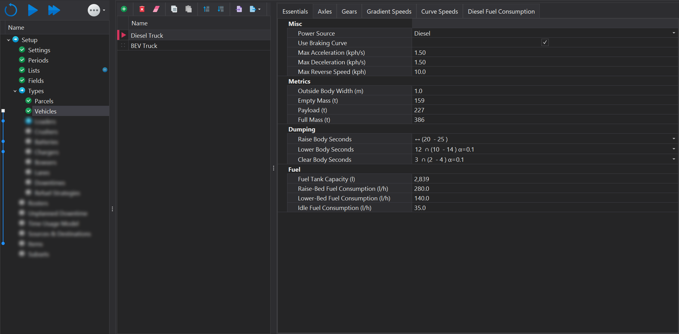
Essentials
Misc
| Input | Description |
|---|---|
| Power Source | The power source for the truck, Diesel or Battery or None. Setting to None will disable refueling/recharging of the truck in the simulation. |
| Use Braking Curve |
|
| Max Acceleration | The maximum rate of acceleration in kph/s (how much the velocity in kph, changes every second) that a truck may experience during the simulation. |
| Max Decceleration | The maximum deceleration rate that a truck will undergo during the simulation. |
| Max Reverse Speed | The maximum speed the truck can travel when reversing. This is used when spotting under load units and at tip heads. |
The 'Max Deceleration' value also serves as the minimum deceleration. This ensures safety within the simulation environment where other trucks are present. This means a truck may travel downhill at a speed below the limit; if it exceeds this speed, its deceleration rate could drop below the minimum threshold.
Metrics
| Input | Description |
|---|---|
| Outside Body Width (m) | The truck's physical width is used to scale the model accurately in the animation. This value is cosmetic only and does not impact performance. |
| Empty Mass (t) | The empty weight of the truck. This value usually comes from the OEM handbook. |
| Payload (t) | The maximum payload the truck can carry. The actual payload the truck will carry will be determined during the simulation run due to the fact bucket payloads can be a stochastic input. |
| Full Mass (t) | The combined weight of the empty truck and the payload. This field is calcualted and can't be edited. |
Dumping
| Input | Description |
|---|---|
| Raise Body Seconds | The duration, in seconds, required for the truck to raise the tray. This input may be stochastic. For more information, please see the following link |
| Lower Body Seconds | The duration, in seconds, required for the truck to lower the tray. This input may be stochastic. For more information, please see the following link |
| Clear Body Seconds | The duration, in seconds, needed for the tray to be completely emptied of material. This input may be stochastic. For more information, please see the following link |
Fuel / Power
The inputs below appear when Diesel has been selected as the power source.
| Input | Description |
|---|---|
| Fuel Tank Capacity (l) | The capacity of the truck's fuel tank, measured in litres. |
| Raise-Bed Fuel Consumption (l/h) | The fuel consumption, in litres per hour, when raising the tray. |
| Lower-Bed Fuel Consumption (l/h) | The fuel consumption, in litres per hour, when lowering the tray. |
| Idle Fuel Consumption (l/h) | The fuel consumption, in litres per hour, when the truck is idling. |
The inputs below appear when Battery has been selected as the power source.
| Input | Description |
|---|---|
| Raise-Bed Fuel Power (kW) | The power consumption, in kilowatts, when raising the tray. |
| Lower-Bed Fuel Power (kW) | The power consumption, in kilowatts, when lowering the tray. |
| Idle Fuel Power (kW) | The power consumption, in kilowatts, when the truck is idling. |
Axles
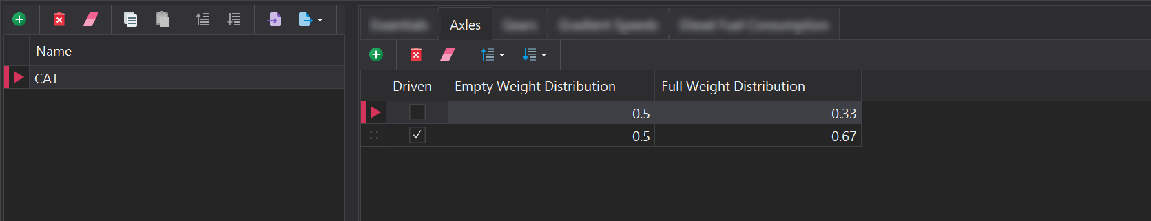
In the Axles tab, the individual axles of the vehicle must be configured. You can add or remove axles using the toolbar located at the top. Each axle entry should specify both the empty and full weight distribution. Additionally, the driven axle(s), which provide power to the ground, must also be identified
Maximum Useable Force
The usable force is essential for determining the maximum acceleration a vehicle can achieve without wheel slip. It is calculated by combining the weight over the drive wheels with the coefficient of traction, which together determine the amount of usable force available before wheel slippage occurs
If the maximum force available at the wheels is 100,000 kgf, utilising the full force would lead to wheel slippage. Consequently, the truck is limited to 92,400 kgf, resulting in reduced acceleration.
In contrast, if the maximum force at the wheels is 90,000 kgf, this entire amount can be applied without causing wheel slippage.
Gears
In the Gears tab, you can define the transmission gears for each vehicle. After specifying the gears, you can set the associated acceleratation (rimpull) and braking (retard) data for each gear. For battery-powered trucks, additional options will appear to manage power usage and regenerative braking.
Gears can be added or removed using the tools located in the top toolbar. Each gear requires a unique name, along with the minimum and maximum speeds that can be achieved in that gear.
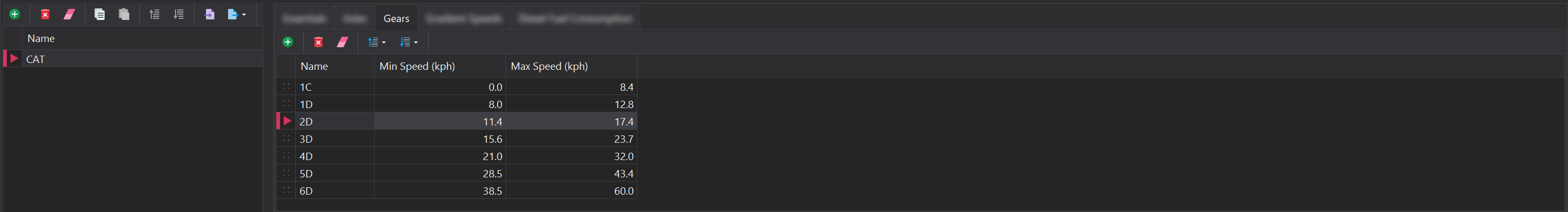
For electric drive trucks, you only need to specify a single "gear", as power delivery is managed through the electric drive system rather than conventional gearing.
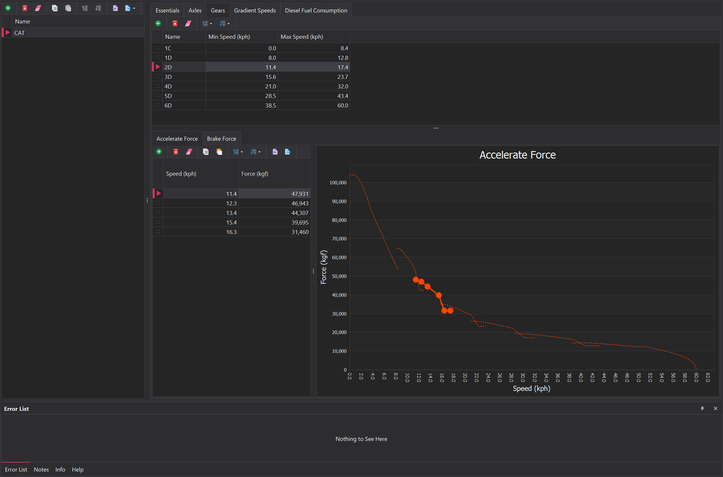
Accelerate Force
The accelrate force, or rimpull, is used to understand how much tractive force a truck can generate at full throttle at a given speed. Since Rimpull represents the force available to overcome resistance (like rolling resistance and grade resistance), it helps tell us the maximum acceleration possible at a given speed, limited by the available tractive force from the engine and drive wheels.
For each gear, you need to specify the applicable speed range along with the corresponding rimpull force in kgf. These values are typically found in the OEM equipment handbook. As you add new speeds, the graph on the right side will automatically update to visually represent the relationship between rimpull and vehicle speed.
Battery Trucks
When 'Battery' has been selected as the Power Source of the vehicle, an additional 'Power' column will appear in the Accelerate Force tab. The column represents how much power, in kW, is consumed at a given speed whilst at full throttle.
Additionally, a new tab appers 'Recharge Force/Power', which has inputs related to regenerative braking. In addition to the speed column, one column represents how much power is genreated and stored in the batteries while fully utilising the regenerative braking. The second is how much braking force is generated while fully utilising the regenerative brakes.
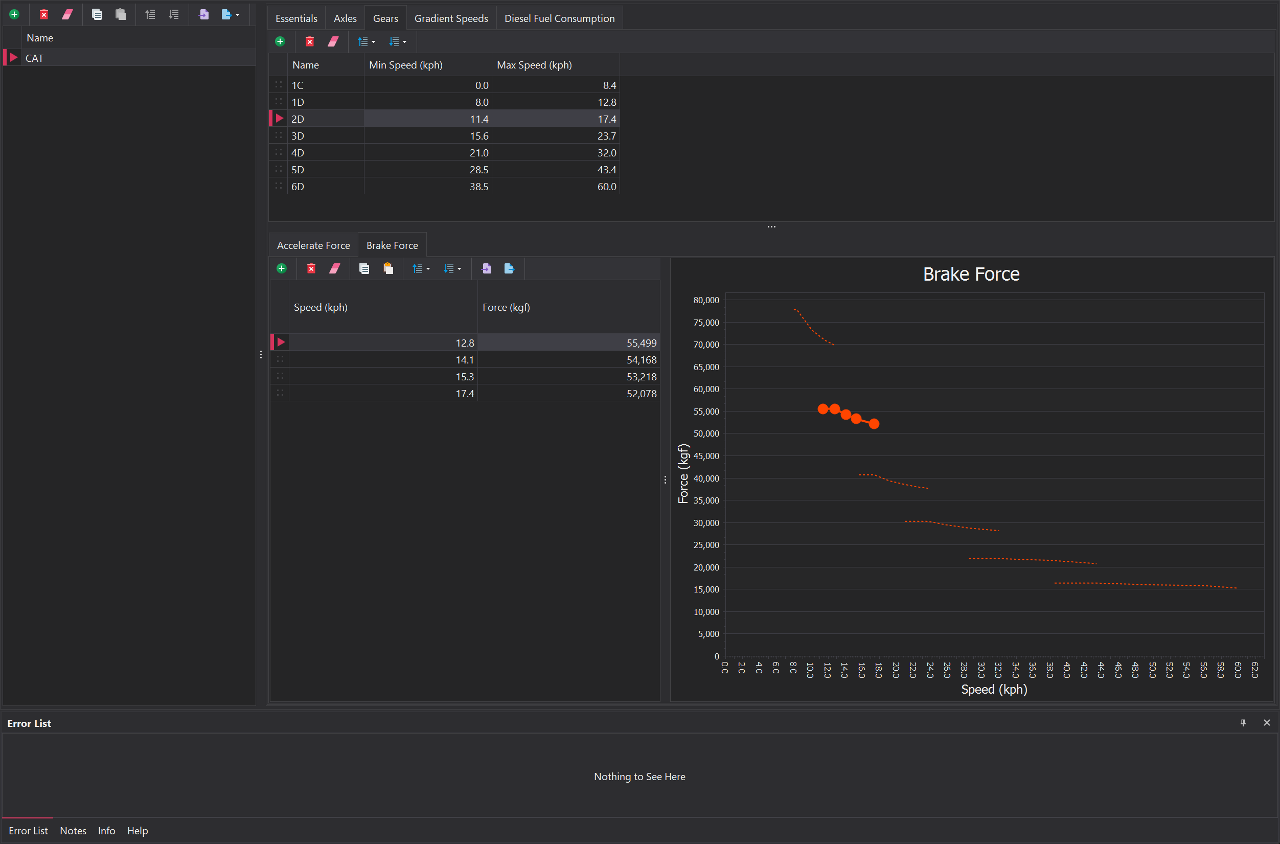
Brake Force
The braking force, or retardation force, indicates how much braking force a vehicle can apply at full brake across different speeds, which directly impacts its deceleration. The braking curve illustrates the force available to counteract the truck's motion, factoring in resistances like rolling resistance and grade resistance.
The Brake Force tab will only be visible if Use Braking Curve has been enabled in the Essentials > Misc.
For each gear, you need to specify the applicable speed range along with the corresponding braking force in kgf. These values are typically found in the OEM equipment handbook. As you add new entires, the graph on the right side will automatically update to visually represent the relationship between braking force and vehicle speed.
The braking curve is utilised to assess whether a truck has sufficient braking force to safely navigate a segment. However, it is not employed for calculating stopping distances. This is due to the existence of multiple braking curves, each configured to address specific scenarios - i.e, - road conditions (wet, dry, or icy).
Instead, we adopt a more streamlined approach by utilising the 'Maximum Deceleration' value to manage the braking rate. By focusing on a single maximum deceleration value, we can effectively control the rate at which the vehicle slows down, regardless of the specific conditions that would typically require distinct retard curves. This higher-level approach allows for a more efficient and manageable simulation while still capturing the essential dynamics of vehicle braking.
Gradient Speeds
Gradient speeds are used to constrain how quickly a truck can travel along road segments with varying gradients. Gradient speeds are configured and represented using interval notion. The following link provides a detailed overview of this concept.
A new range entry can be added or removed using the toolbar at the top. New entries are automatically placed at the bottom of the list and can be repositioned using drag-and-drop. Each range entry requires a gradient (%), along with empty and loaded speeds for the truck. The 'Interval' value is auto-populated based on the gradient and its position in the list.
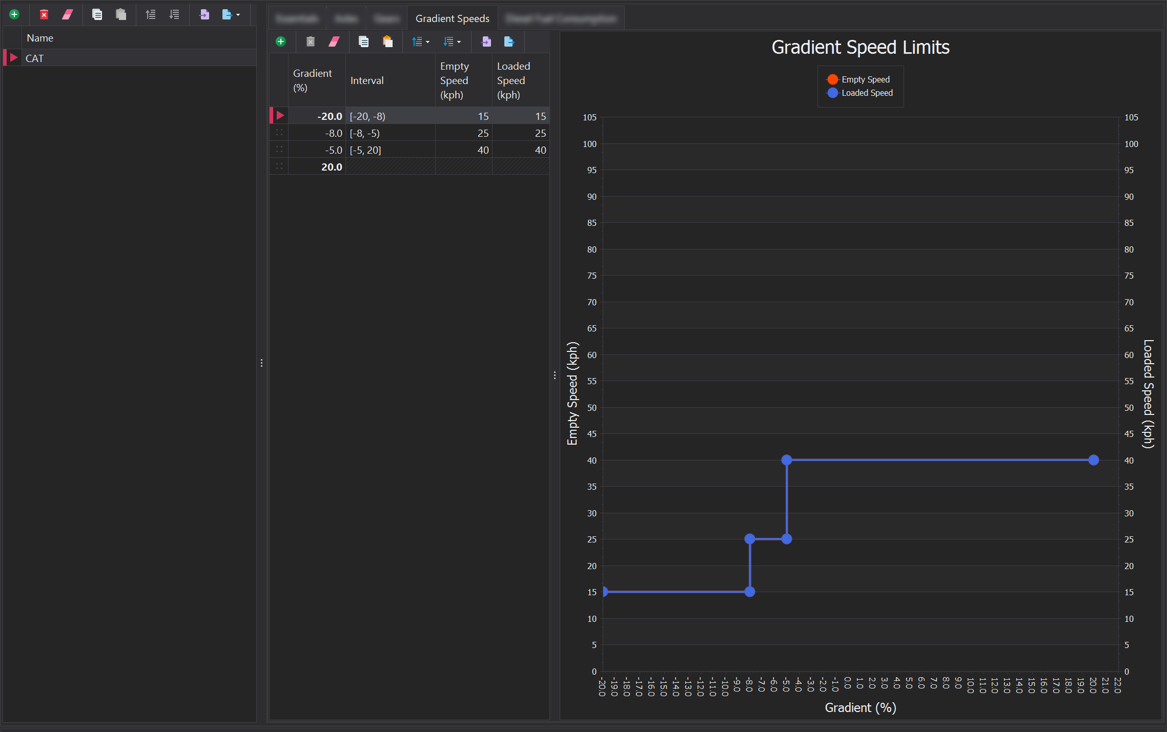
The speeds specified here are the maximum allowable speeds the truck can achieve. However, reaching these speeds is not guaranteed, as actual speed may be influenced by factors such as engine performance and speed limits.
Diesel Fuel Consumption
When 'Diesel' is selected as the vehicle's power source, a fuel consumption curve must be defined. Since trucks require refueling in the simulation, monitoring the fuel level is essential. These fuel usage curves can often be found in the OEM handbook; alternatively, you may need to obtain the data from maintenance records or your Fleet Management System (FMS).
A new entry in the table can be added or removed using the toolbar at the top. Each entry must specify the engine load along with the corresponding fuel consumption.
